


How to Create Geometry in Artec Studio to Reverse Engineer Mechanical Parts
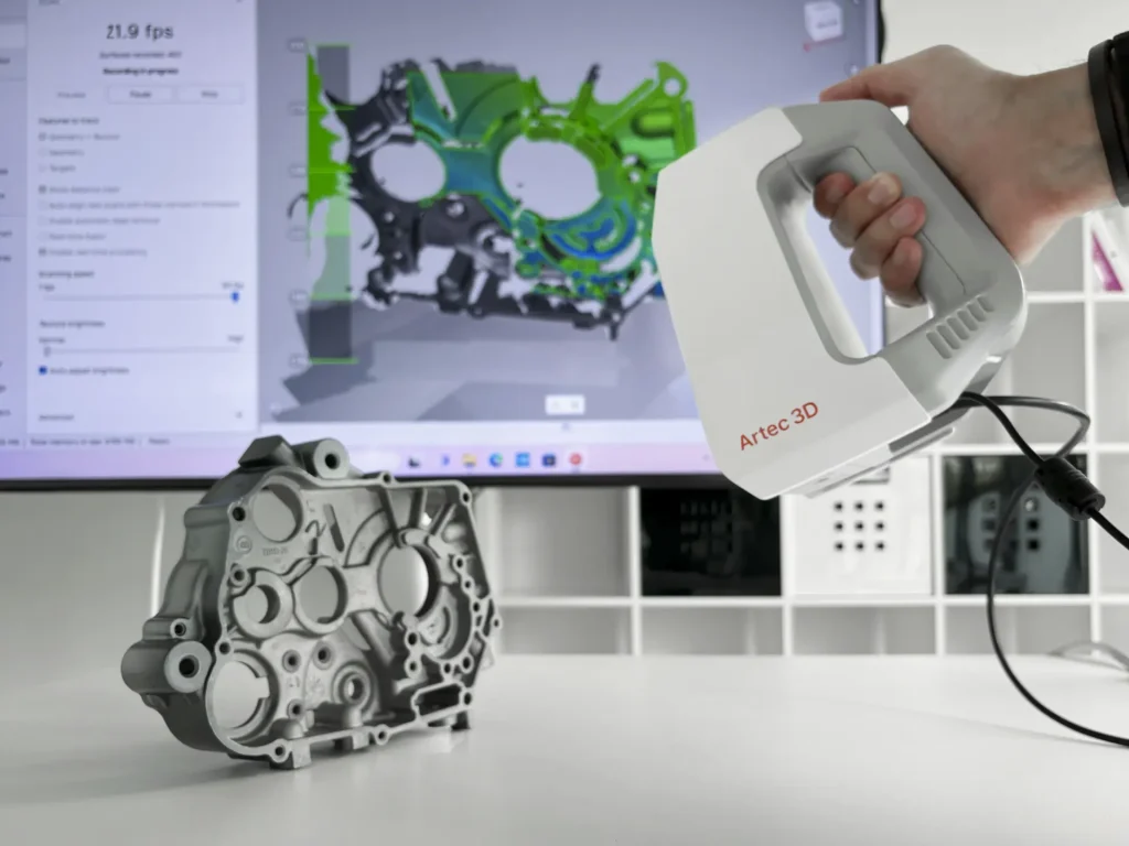
In this video, I’m going to show you how to construct scanned geometry / create geometry in Artec Studio so you can easily reverse engineer mechanical parts. For this example, I’m using a cast rotor baseplate. Let’s look at how it is done.
Starting from Sharp Fusion, navigate to the Construct tab. The first thing I’m going to do is extract a cylinder for the main axis of the rotor. I can use my 2D selection tool, but I’m going to quickly paint two areas around here.
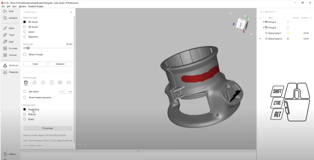
Paint area in Artec Studio to create a plane
I’m going to use the Expanding fitting method and click the fit cylinder button. Next, let’s do a plane for the left side attachment point and the right-hand side as well using the same method.
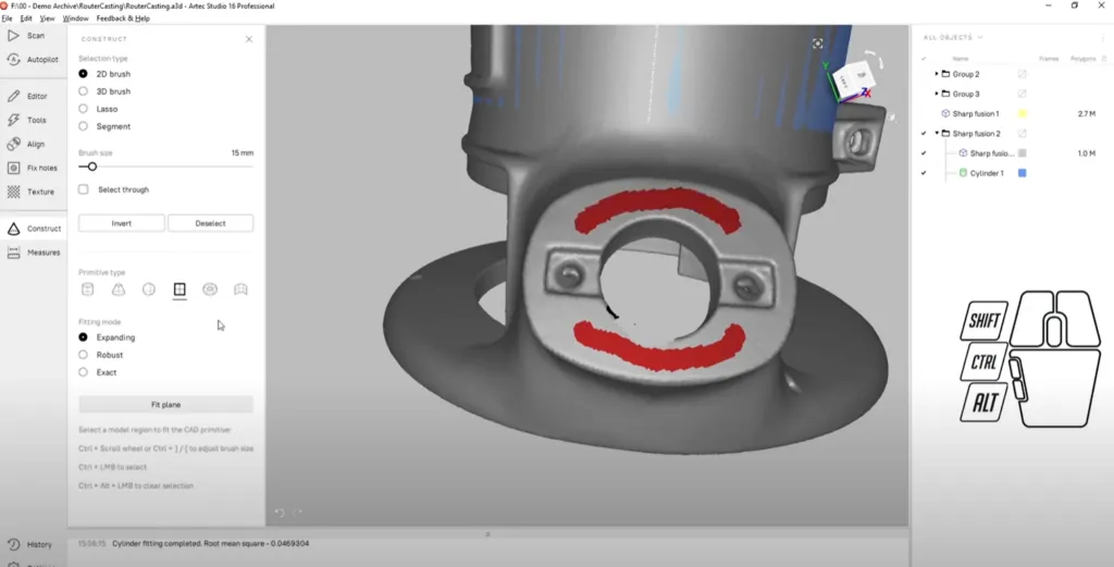
Creating a plane for the left side attachment in Artec Studio
We also need to do a plane for the top. Now, since the top is a little narrower, I am going to use the robust fitting mode to give myself a little bit more room, if I make an improper selection. Any time I clear outside the lines, the Robust Fitting method will do a good job of correcting it.
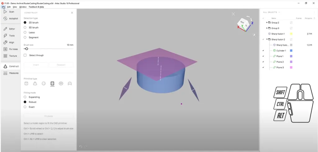
Hide mesh and export in Artec Studio
Finally, I can hide the mesh and export these CAD objects and save them as a STEP file. In just a few easy steps, Artec Studio allows me to create scanned geometry that can be used for reverse engineering our mechanical parts.
Manufacturing Services

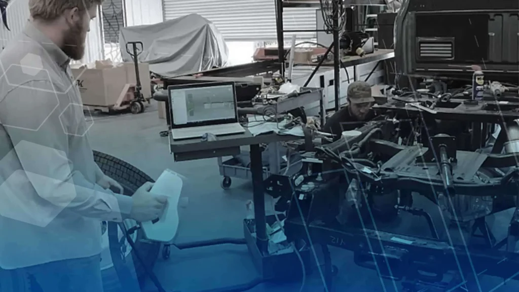
Interested in Advanced Manufacturing?
Contact us today and tell us about your manufacturing requirements