


How to Manage 3D Printing Dimensional Accuracy in FDM Prints
By TriMech Marketing, last updated August 8, 2025
Achieving 3D printing dimensional accuracy is critical, especially when using Fused Deposition Modeling (FDM) for prototypes or production-grade parts. While FDM is affordable and fast, it can introduce dimensional inconsistencies due to factors like layer height, seams, and mechanical chatter.
In this guide, we’ll explore practical tips to improve dimensional accuracy in FDM prints by adjusting key printing parameters and design strategies.
What Affects Dimensional Accuracy in FDM 3D Prints?
FDM printers work by extruding melted filament layer by layer. Because of this process, slight deviations can occur in the X, Y, and Z axes, which affects tolerances and dimensional fit. Common culprits include:
- Improper layer height selection
- Poorly managed seam placement
- Chatter from sudden changes in direction or mechanical instability
1. Match Layer Height to Critical Dimensions
The biggest misconception associated with the FDM layer height is that a finer layer height will increase the accuracy of the print. This is not always the case.
Selecting a finer layer height will, in fact, reduce the toolpath’s footprint, resulting in the ability to fit material in tighter sections along the x-y plane and can improve the overall surface finish of the part. However, with respect to the z-axis, this may slightly offset critical geometries.
Let’s dig into an example to explain this concept better.
We want to print the electronics enclosure in the image below with the trapezoid cutout as a critical feature that needs exact heights of 0.38″ and 0.54″. Our printer has a resolution capacity of .010 and .007 of an inch. Both these z-axis dimensions are easily divisible by the .010 of an inch layer height, but not easily divisible by the .007 of an inch layer height.
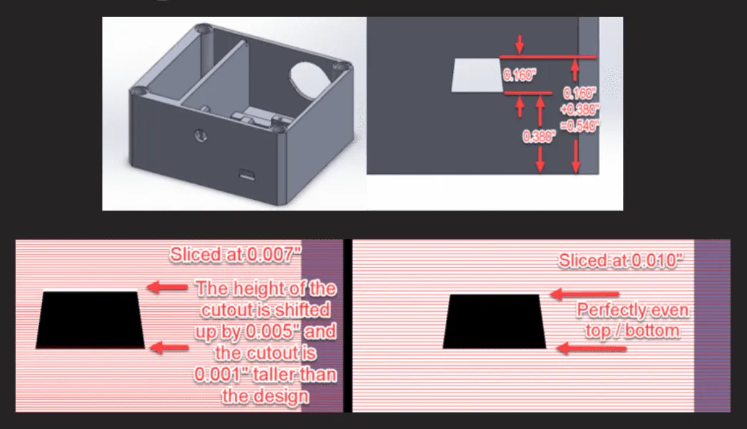
This will result in the toolpath shifting the top of the cutout by .005 of an inch and making the base of the cutout higher by .001 of an inch.
Best Practice:
- Choose a layer height divisible by critical Z-dimensions. Finer resolution may in fact result in the critical feature deviating from its actual position.
- Don’t default to the finest setting. Match the layer height to your design intent.
2. Manage Seam Placement to Improve Surface Accuracy
A seam in FDM printing is a linear blob on the profile of the part that illustrates the location where the tool path begins and ends, as you can see from the picture below of the small vertical line.
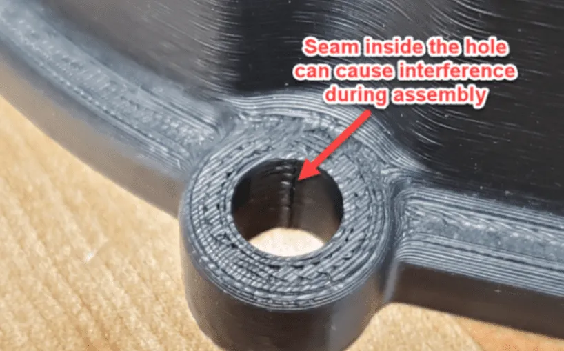
In most cases, slicing software such as GrabCAD will do a decent job of hiding the seams by placing them in a sharp corner. This is not feasible with geometries such as holes or round slots. If you are able to post-process the part, you can undersize the hole in CAD by about .015 of an inch in diameter and use a reamer to chase the hole. If the hole is to act as a clearance hole and doesn’t need to adhere to precisely fitting parts then you can add a corner to the internal diameter of a hole.
How to use GrabCAD Print to hide seams:
- Begin by inserting your model into the build tray using the Add Models dropdown. For this to work correctly, you want to import a file type that is not a body file, like an .STL.
- Now that the model has imported, select the critical face. In this case, the critical face is the inside of the hole.
- Next select Model Settings > Face and make sure to check the “avoid seams” checkbox.
This will help reduce the total size of the seam. However, it will not completely remove it if it risks the integrity of the part.
3. Reduce Mechanical Chatter
Chatter refers to vibration marks or ripple effects around curves and corners. When a FDM 3D printer makes a corner, the head ramps up or slows down. The movement of the extruding filament may be slightly out of sync, which can result in channel marks around the curve.

How to reduce chatter:
- Ensure that all of your rounds have a minimum radius of 1/10 of an inch. This provides sufficient time for the tool to ramp up and slow down as it prints.
- Slow print speeds slightly for high-precision parts. Chatter are caused by the print head slowing down or speeding up quickly.
- If you have a belt-driven system, it is important to ensure that the bolts and pulleys aren’t worn out or dirty, because that can also cause geometrical deviations in your prints.

Written by TriMech Marketing
TriMech Manufacturing, a division of the global TriMech Group, is a strategic technology and business solutions paartner for designers, engineers, and manufacturers.
With a legacy spanning decades, the division focuses on helping clients design, build, and deliver products faster through a comprehensive ecosystem of manufacturing tools and expertise.
Related TriMech Solution
Learn more about the solutions featured in this Article:
Need a Quote for Advanced Manufacturing?
Contact a TriMech manufacturing expert today and get answers to your questions
Related Content
More advanced manufacturing content from the TriMech team