


3D scanning is an increasingly popular technology for manufacturing. In this video, we will walk through how to reverse engineer with a 3D scanner. You will learn how to integrate the scanning process into your design workflow, and we’ll share some best practices to get the most accurate and efficient results from your 3D scans.
Why Reverse Engineer with a 3D Scanner?
3D scanning allows users to quickly and accurately capture complex geometries, making it easy to digitize physical objects for reproduction, redesign, or documentation. 3D scanners can be used in a range of applications from automotive/mechanical, quality control, design process, metrology, healthcare and reverse engineering. Because of their many use-cases, industries including medical, industrial design and manufacturing, science and education, 3D services, animation and graphics, and human sculptures are embracing this technology.
Benefits of using a 3D Scanner for Reverse Engineering
- Fast and accurate way to capture complex geometries
- Ideal for parts without existing CAD models
- Improves the product development process
- Enables rapid prototyping, customization, and digital archives
Step-by-Step Process:
Reverse engineering, also referred to as backwards engineering, is the process of extracting information from pre-existing objects and reproducing them based on the information gathered.
As the flowchart shows below, the process of reverse engineering starts with a physical object that you want to replicate or improve. First, 3D scan the object to capture its shape and reconstruct its surface as a digital model. From there, you can 3D print the object or detect features to perform surface modeling or feature-based modeling in CAD for design modification, analysis, or manufacturing.

Process of Reverse Engineering
More specifically, there are five steps for reverse engineering with a 3D scanner:
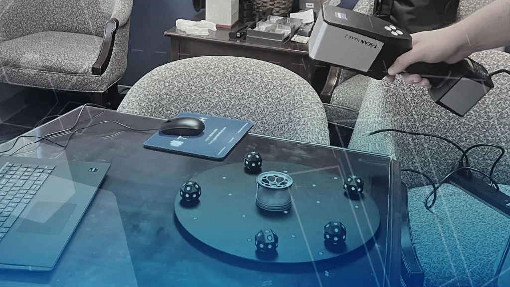
- Prepare the part – this can include adding reference stickers or spraying reflective areas of the parts.
- 3D scan the part – the 3D scanner produces triangular meshes, or point clouds, often tied to color photographs. If the object needs to be scanned from multiple sides, the scanning process can be paused and restarted for each new pose.
- Process the scan data – from there, the datasets are aligned and merged into a single digital model with a common reference system. If necessary, the color data is wrapped onto the model.
- Import into CAD software – the data is exported to be used in other software or retained for study.
- Reconstruct the model – with the data, an engineer could use the scan to rebuild or simplify parts without needing the original digital file.
Our experienced engineer also prepared this detailed webinar on the full reverse engineering process if you want to learn more about the process from 3D scan to CAD model.
How will Reverse Engineering with a 3D Scanner Impact Your Workflow?
Reverse engineering allows scan to print with zero manipulation and scan to CAD with the ability to create models and assemblies with nowhere near a CAD/CAE configuration. Some of the capabilities of a scanned model include surface extraction, based modeling and hybrid modeling.
Plus, with the add-in for SOLIDWORKS, users can efficiently work on mesh healing, feature extraction, auto surface features and use SOLIDWORKS workflow and interface. Check out this video on how SOLIDWORKS helps create a full featured 3D model in a reverse engineering project.
Best Practices for Reverse Engineering with a 3D Scanner
- Scanning Background – Choose your scanning background carefully – lots of color/texture works best. Woodgrain surfaces are especially effective because the small variations and knots help the scanner orient itself in space.
- Scanning Distance – Keep an optimal distance between you and your scanner. Use the visual feedback on your computer: If you get too close your object on your screen will highlight red. And if you’re too far, it highlights blue. The Artec Studio gives us a histogram that helps us determine if we are at an optimal distance away from our scanning object.
- Scanner Movement – Move the scanner smoothly while capturing your object. Avoid sudden movements, as these can cause the scanner to lose tracking.
- On Screen Scan – Focus your attention on the screen, not the object, to make the most of the on-screen feedback and improve your scan quality. This is probably one of the hardest things for people to learn when they start out scanning, but it starts to come naturally after you’ve done just a couple of scans. Our hand-eye coordination takes care of most of this, and it becomes easy to move our scanner with one hand and keep our eyes on the screen.
- Object Movement – If scanning an animal or person, make sure they keep as still as possible to avoid distorted data. Even a little movement can result in misaligned features, like a nose coming out of the forehead or ears not lining up properly. While you can take more scans and stitch them together, it’s always easiest to get things right the first time.
If you want to dive deeper into how to optimize your reverse engineering workflow and maximize scan-to-print capabilities, check out this webinar on the 3 secrets to a complete engineering solution.
You will also learn from how our engineer fixed a squeaky ceiling fan and succeeded in reverse engineering jet ski parts using 3D scanning and 3D printing.
Conclusion
Reverse engineering with a 3D scanner transforms how we approach product design, repair, and innovation. It enables users to capture complex geometry from objects to quickly create parts, improve existing design, or document components – without the need for original CAD data. 3D scanning makes the process faster and more accurate whether you are working on consumer products, machinery, or prototypes.
Manufacturing Services
Latest Articles


Interested in Advanced Manufacturing?
Contact us today and tell us about your manufacturing requirements