


Cold Metal Fusion (CMF) is emerging as a leading option for batch production of complex metal components thanks to its combination of affordability and high throughput. It delivers mechanical properties comparable to sinter-based manufacturing methods such as Metal Injection Molding (MIM) while offering greater design flexibility and provides far better scalability than laser‑based metal additive manufacturing methods.
This article discusses:
- How the CMF process works compared to other metal manufacturing methods.
- How CMF is applied in industrial environments with different materials.
- Key questions surrounding this emerging technology.
What is Cold Metal Fusion?
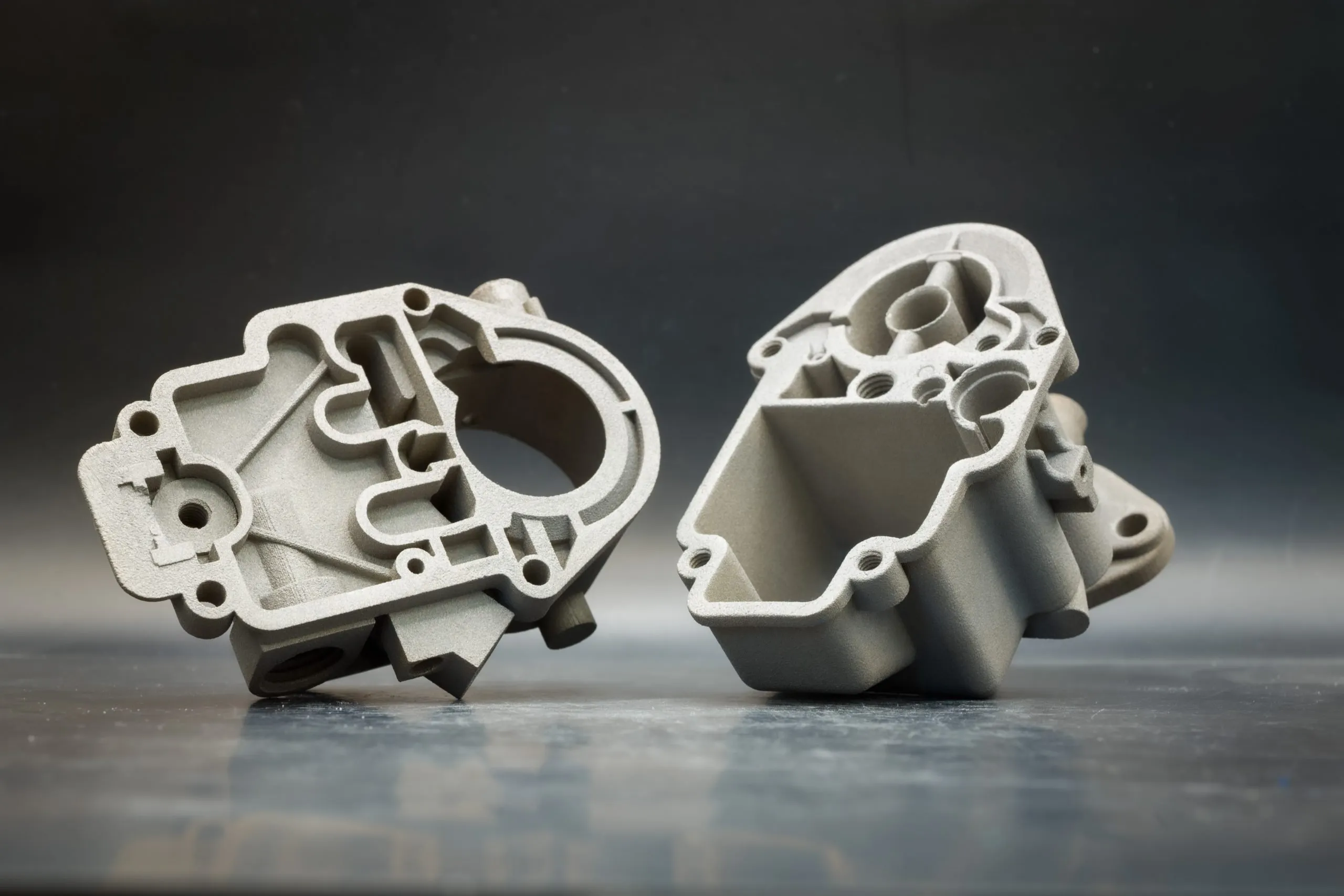
Cold Metal Fusion (CMF) is a sinter‑based 3D printing technology for batch production of complex metal parts. It allows economical production of 10 to 1,000 parts per year with broad material options.
Essentially, it integrates existing processes including Selective Laser Sintering (SLS), debinding, and sintering, to make metal 3D printing more accessible.
Headmade Materials GmbH, the creator of CMF technology, developed the proprietary feedstock materials that form the core of the entire process. Metal particles are encapsulated with classical polymer powder that acts as binder that melts during SLS printing.
How Does Cold Metal Fusion Work?
There are three key steps in the CMF process: printing, debinding, and sintering. But a more comprehensive process looks like this:
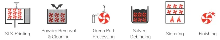
Step 1: SLS printing
We print on standard polymer SLS machines at low temperature (<80 °C; ~50 °C often sufficient). This is why the process is called “cold”. When compared to traditional melting-based metal printing technology like LPBF/SLM/DMLS, this temperature only melts plastics during the printing process. The green parts acquired from this step are polymer–metal powder composite that behaves more like firm plastic rather than fully dense metal.
Step 2: Depowdering
Once the powder bed has cooled, the loose, non-melted powder surrounding the green parts is removed.
The rest of the loose powder can be reused for the next build.
Step 3: Machining (Optional)
Before the sintering step, the green parts are strong enough to undergo precise machining such as milling, grinding, or drilling. This is particularly valuable for Titanium and Inconel, which become extremely hard and expensive to machine after sintering. Machining at the green stage is significantly easier and cheaper.
Step 4: Debinding
The green part is immersed in a solvent heated to 30 to 40 °C, which removes most of the binder from the metal structure and produces a component known as the brown part.
Step 5: Sintering
The parts are placed in a furnace and gradually heated to the sintering temperature, allowing the slow heating process to remove the remaining binder.
At the metal’s sintering temperature, the metal particles fuse together to form a dense solid part. The parts shrink evenly in the X, Y, and Z axis, by approximately 13% for Ti-64. The sintered part typically reaches a density of 97% to 99%.
Step 6: Finishing
Post-processing includes CNC machining, grinding, polishing, sandblasting, and anodizing. Parts can be easily treated with hot isostatic pressing (HIP) or heat treated to achieve desired density and grain structure.
How CMF Compares to other Metal Manufacturing Methods
As a relatively new technology introduced in 2021, Cold Metal Fusion is often compared with traditional metal manufacturing technologies, such as powder metallurgy methods like metal injection molding, additive manufacturing like LPBF, as well as binder jetting and even casting.
CMF vs Metal Injection Molding (MIM)
With comparable mechanical properties of powder metallurgy methods including Metal Injection Molding (MIM), CMF wins over the economical production of metal parts with:
- Small to high volume: Due to high tooling costs, MIM often does not allow the range for first prototypes.
- Design complexity: MIM has tool limitations on design freedom.
- Large size: Due to tool design and sintering limitations, MIM is currently often limited to the part size of a fist and a few hundred grams in weight. With CMF, though the sintering limitation still does apply, the production of complex parts with a height of more than 8.5 inches or a weight of a few kilograms is possible.
| CMF | MIM | |
|---|---|---|
| Cost | Lower at small to medium volumes (10-1000) | Cost-effective only at high production volume (>1000) |
| Design freedom | Same geometric freedom as SLS for complex parts | Complex parts require complex (or impossible) tooling |
| Part size | Only limited by SLS printer and furnace | Small parts |
| Accuracy | ~±125 µm, better if optimized | High accuracy for small parts (typical tolerance 0.3–0.5%) |
| Strength | Comparable mechanical properties, slightly lower stiffness | Stronger and stiffer due to higher density, near wrought levels |
CMF vs LPBF, SLM, and DMLS
As the leading technology in metal 3D printing, Laser Powder Bed Fusion (LPBF), also known as Selective Laser Melting (SLM) and Direct Metal Laser Sintering (DMLS), continues to face limitations in part throughput and market adoption due to its high costs and safety considerations.
CMF offers several key advantages:
- No support structures are required, resulting in faster production and lower costs.
- Excellent performance on large parts, where DMLS normally struggles. CMF can accommodate parts sizes approaching those seen in sand casting or high-volume investment casting.
- Significant cost savings, often up to three times cheaper than DMLS, based on our experience of producing titanium parts.
CMF limitations compared to LPBF:
- Rougher surface finish: CMF does not achieve the same fine resolution as LPBF, typically producing surfaces in the range of 11 to 13 Ra. There are post finishing services available.
- Application limitations: some aviation parts require federal certification tied to specific LPBF systems. Because CMF is a newer technology, it has not gone through the same validation processes that many LPBF machines have completed.
| CMF | LPBF/SLM/DMLS | |
|---|---|---|
| Cost | Lower due to equipment setup, and no support structure needed | High with high-power laser systems, inert chambers, expensive powder, support structures |
| Speed | Fast with only melting plastic binder, no supports, and batch-based debinding & sintering | Slow due to laser scanning bottleneck, need for support structures, and high energy densities |
| Part size | Only limited by SLS build volume and sintering furnace, both available in many sizes, supports larger and bulkier parts more easily | Often limited to small‑to‑medium build chambers |
| Accuracy | ±125 µm accuracy | More accurate especially for small, highly detailed components |
| Strength | Isotropic PM‑grade strength | Highest density and strength, but with anisotropy |
| Design freedom | Extremely high | Limited by the need for support structures |
| Production volume | From low to medium-high volume | For high-value low-volume parts |
CMF vs Metal Binder Jetting
Due to similar workflows (print, debind, sinter) and comparable MIM-like metal properties, CMF is also frequently seen as an alternative and even a competitor to binder jetting. Below is a comparison of the key considerations:
| CMF | Metal Binder Jetting | |
|---|---|---|
| Cost | More economical | Higher CapEx and binder cost |
| Speed | Faster overall | Can match throughput only when densely packed |
| Part size | Broad | Best for small–medium; tall/heavy parts more constrained |
| Green part strength | High | Low |
| Shrinkage | Uniform shrinkage, ~12%–15% (XYZ) | Anisotropic shrinkage (e.g., ~17–19% in XY, 22–26% in Z) |
CMF vs Titanium Casting
Titanium is a challenging and hazardous material to cast, often requiring longer lead times. Many casting facilities are fully booked for titanium defense applications, sometimes for more than 12 months. In these situations, CMF becomes an increasingly attractive option, offering advantages such as:
- Greater design freedom
- No tooling required
- Much shorter engineering cycles
- Large and heavy parts
- More consistent, defect‑free parts with reliable mechanical performance
- Economies at mid-volumes
Cold Metal Fusion Applications
CMF technology has been increasingly used in the defense, aerospace, medical, and energy sectors. These industries benefit from mid-volume runs (10 to 1000 units), where CMF delivers strong performance and efficiency.
CMF excels in industrial applications that require both precision and cost-efficiency, including impellers, medical implants, auto components, industrial machinery, and defense articles.
CMF is also becoming a popular alternative for short-run production, reshoring efforts as an alternative to die casting, and bridge-to-production needs traditionally handled by investment casting.
There are some applications that benefit from the CMF green part post-processing step:
- Functional surfaces: by optimizing surface quality and component geometries at the green part stage, machining of the final components can be reduced to a minimum.
- High-precision components: Applications with requirements for planarity, thin wall thicknesses, or fine details benefit from the ability to address these needs early and cost effectively.
- Lightweight aerospace and medical products: Titanium or Inconel can be machined with precision and time efficiency.
Materials Compatible with Cold Metal Fusion
CMF can use the full material spectrum of powder metallurgy, such as injection molding, forging, HIP, hot pressing, etc. It supports edged particles, coarse powders or fine powders between 10 to 60 µm, allowing manufacturers to choose the optimal primary particles for different requirements.
Currently available materials from Headmade Materials:
- Stainless steel 316L: Commonly used in medical engineering, including surgical tools and implants due to its stability and safety in human‑contact or harsh environments.
- Stainless steel 17/4PH: Popular in aerospace, industrial machinery, tooling, and high‑load structural parts.
- Tool steel M2: Exceptional red hardness, abrasion resistance, and strength at elevated temperatures, making it ideal for tooling applications.
- Titanium Ti6Al4V: Widely used in aerospace, medical implants, motorsport, and lightweight structural parts.
- Tungsten alloys: Suitable for cutting tools, dies, radiation shielding, balance weights, and military components.
- Inconel 625: Used in aerospace engines, heat exchangers, chemical processing, and high‑temperature structural components.
Materials under development:
- Tool steel H13: High toughness, thermal fatigue resistance, excellent strength at elevated temperatures.
- HAYNES 282: a nickel‑based superalloy developed for high temperature structural applications; used in aero and industrial gas turbines, heat exchangers, aerospace structures, and pressure‑containing equipment.
3 Must-Know Questions About Cold Metal Fusion
How strong are CMF parts?
CMF uses a process similar to traditional powder metallurgy, and thus the resulting metal part properties are comparable to those produced by established PM methods.
As seen from the pictures below, CMF parts made from Stainless Steel 316L and Titanium Ti6Al4V achieve or exceed PM requirements (ASTM and ISO standards) for yield strength, tensile strength, and elongation.


Additionally, both grain structure and density of CMF parts meet the high standards expected in quality powder metallurgy.
Grain structure: In the CMF process, the metal powder itself remains unaffected, preventing the formation of anisotropic grain structures commonly seen in LPBF Powder Bed Fusion (PBF).
Density: Acceptable density (96% to 98%) depends on material, printing parameters, and sintering conditions. Typical results include:
- 97% density for Stainless Steel 316L
- Up to 100% density for liquid phase sintering alloys
- Up to 99% repeatable density with optimized process parameters
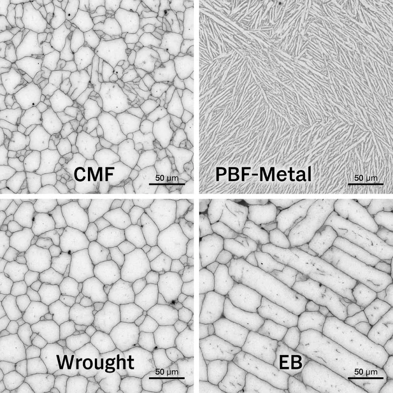
Sintering creates a lot of strong cross-section – CMF vs PBF vs Electron Beam vs Wrought metal structure
What about dimensional accuracy and surface quality of CMF parts?
While tradeoffs still exist compared to milling or MIM, CMF delivers dimensional accuracy of approx. ±125 μm and can be higher with optimized design and processing. If tighter tolerances are required, post processing can be applied either before sintering (on the green part), or after sintering (on the final metal part).
At TriMech, all our CMF parts have demonstrated excellent accuracy – they come out precise both from the SLS printer and after sintering, typically within 5 thou, comparable to what we see with MIM.
Surface quality of CMF parts is comparable to LPBF or Binder Jetting. When smoother surfaces are required, machining or polishing can be applied before or after sintering.

Is CMF really cheaper and more accessible than traditional metal 3D printing?
Yes. Many 3D printing cost examples appear artificially low because they rely on unrealistic assumptions. For example, 100% machine utilization, excessively high packing density, bulk‑rate material cost, and the exclusion of labor, post‑processing, scrap rates, and material loss. If you include all cost factors from powder to final metal part in a real-world setting, CMF is one of the most cost-efficient approaches to manufacturing metal parts. Our projects show that CMF parts can be three times cheaper than the DMLS method.
Cost factors of CMF production:
- CapEx: Full chain (SLS, debind, and sinter) starts at around $23K, with larger build space and throughput than most DMLS machines.
- Materials: The powder is 100% recyclable since the cold process leaves the unsintered material unaffected by the heat.
- Low print temperature saves heating time and energy.
- No inert gas: Plastic-coated metal particles are not exposed to air, preventing oxidation of the metal.
- Less post-processing: No need for cross-linking, heat treatments, and support removal.

FAQs
Who developed CMF and who is adopting it?
Headmade Materials is the developer of CMF technology, by innovating the proprietary material used in the process. The ColdMetalFusion Alliance brings together hardware makers, MIM companies, post processing partners, materials specialists, simulation and quality tool providers to make CMF an industry-wide movement. Industrial users such as Element22 use CMF to produce large impellers and automotive gears.
Do CMF parts require heat treatment or stress-relief annealing?
Because CMF parts exhibit isotropic grain structures without high internal stresses, they generally do not require heat treatment or stress-relief annealing, unlike many other metal 3D printing technologies.
Final hardness is determined by the base alloy and the sintering process, not by the 3D printing step itself. Hardness values of up to 56 HRC (material dependent) are achievable without additional post treatment.
Metal parts used in specific areas of application (e.g. aerospace) are often post-processed by using hot isostatic pressing (HIP). It is recommended to optimize the part design and parameters to avoid an additional post-processing step.
What to pay attention to when designing for the CMF process?
There are also some design limitations in using the CMF process.
- The wall thickness should be at least 1.0 mm up to a maximum of 25.0 mm to guarantee sufficient stability but also to ensure a short debinding time.
- Excessive overhangs should be avoided as these have limited stability during the sintering process.
- Necessary overhangs can be mitigated by printing sintering support structures.
Are there any requirements for software used in the CMF process?
No specific software is required for the CMF process – you can use any standard software available. This includes CAD, slicers, and sintering simulation.

Written by Sophie Jin
Sophie (Huiyu) Jin is an SEO/PPC Specialist at TriMech, where she focuses on digital marketing strategies for their additive manufacturing and CAD business units.
Prior to joining TriMech, Sophie worked as a business journalist both in Canada and China, covering various industries, particularly tech companies.
Related TriMech Solution
Learn more about the solutions featured in this Article:
Need a Quote for Advanced Manufacturing?
Contact a TriMech manufacturing expert today and get answers to your questions
Related Content
More advanced manufacturing content from the TriMech team