


How We Make a Thunder Roadster Faster: From Scanning to Manufacturing
To optimize the performance of our Thunder Roadster, our team leveraged TriMech’s comprehensive hardware and software solutions—from 3D scanning and SOLIDWORKS Simulation to FDM 3D printing.
Related Topics
Solutions featured in this Case Study
 3D Printers
 3D Printing Materials
 3D Scanners
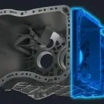 Design Your Products
 Digital Manufacturing Solutions
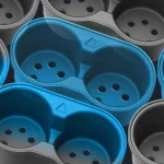 Make Your Products
Racing, by nature, is a competitive business and all racers are trying for the top spot. To get the best performance of a Thunder Roadster, our team used TriMech’s hardware and software portfolio, from gathering data by 3D scanning the entire outside of the racing car, to converting the data into a usable SOLIDWORKS 3D CAD model with which we evaluate, verify and modify the vehicle for ultimate performance.
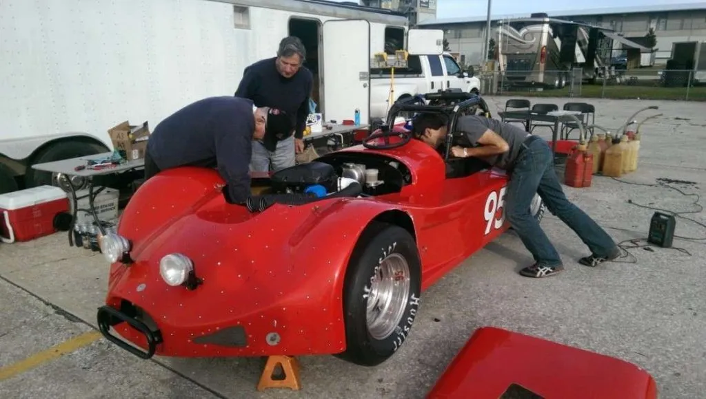
The Thunder Roadster
The Thunder Roadster is a car designed to both look good and go fast. It has a popular following because it was designed to be more accessible to younger drivers and you don’t need several corporate sponsors in order to race. Under the shell is a sprint car-type roll cage and a driver-friendly long wheelbase. A fan (and driver) favorite is the open cockpit design for superior visibility.
One of our Senior Application Engineers, Ryan Zeck, has been racing since before he was nine years old and has always had a passion for going fast. Watch our introductory video below as we talk to Ryan and go over our project plan for customizing his Thunder Roadster:
Tools We Need
To get the best performance possible and customize and upgrade some of the Thunder Roadster’s components which tend to be limited, we look into TriMech’s hardware and software portfolio and utilize this combination of products:
- ARTEC 3D Scanners and Geomagic Design X to provide a digital model of the Roadster for us to base our simulations on and create custom components around.
- SOLIDWORKS Flow (CFD) to provide insight into the aerodynamics of the Thunder Roadster body and engine airflow.
- SOLIDWORKS Simulation (FEA) to provide insight into suspension performance.
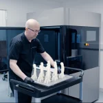
- Stratasys 3D printers to manufacture the custom end-use products in a timely and cost-effective manner out of the strong/light-weight materials we need.
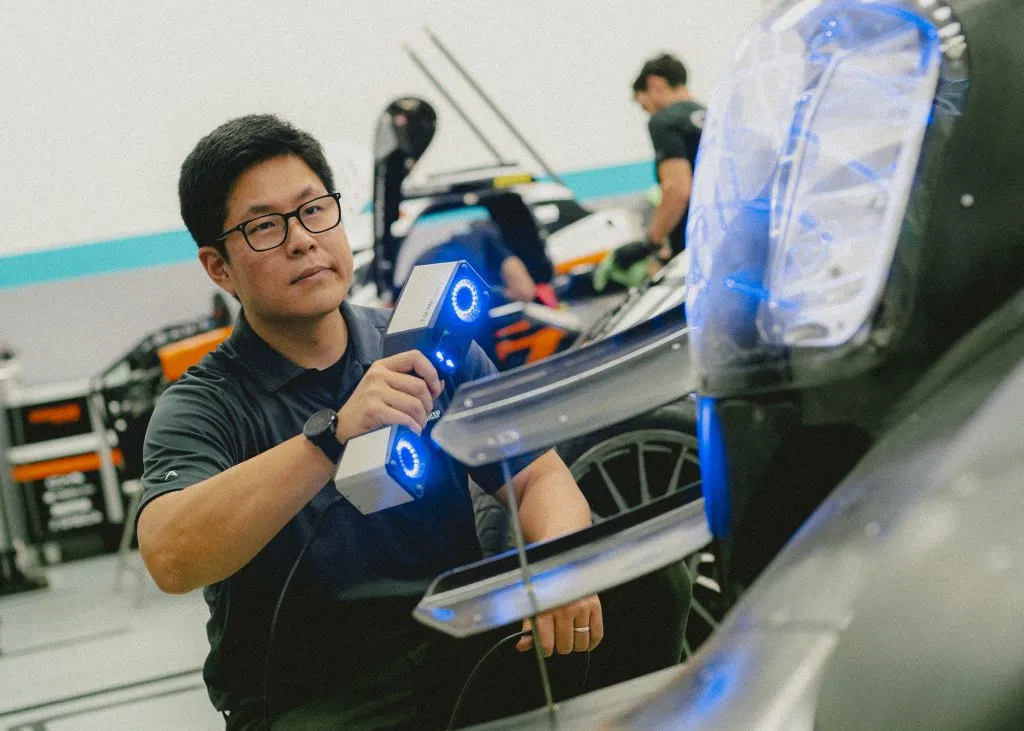
Step 1: Scanning
3D scanning is being used more in many industries for reverse engineering and product customization due to the precise results and lowered technology costs. We used Artec 3D scanners to capture details and data from the Thunder Roadster and then recreate or improve upon it.
Making a 3D Model
Scanning an object in Artec Studio is easy thanks to its 3D radar mode. The software shows us when Chris is holding the scanner at the optimal distance by visualizing the real-time 3D data in green. If the scanner moves a little too close, the image turns red; a little too far back and it will turn blue, making sure we’re reminded to be at optimal scanning distance.
While there are many ways to generate advanced features to fine-tune the mesh in Artec Studio, Autopilot mode allowed us to save time, automatically guiding us through the post-processing steps and using the best algorithms available to build Ryan’s car model as fast as possible.
To take the scanned data and get a useable model, we had to do a little bit of post-processing. Removing extraneous scan data like the surface the model was sitting on, extraneous points and a few other considerations ensure that we get a good model.
We have two different software programs available to us to take a scan from Artec Studio:.
- Geomagic for SOLIDWORKS – A complete scan-to-CAD solution, Geomagic for SOLIDWORKS allows for the fastest scan to model generation. Once the scan is completed, we can export and edit the model directly into SOLIDWORKS. Since Geomagic for SOLIDWORKS operates directly inside SOLIDWORKS, we can take advantage of using the same familiar tools and workflows to create models from scan data with ease.
- Geomagic Design X – a professional 3D scanning software solution, allowing for the most complete set of features to produce feature-based, editable models directly for SOLIDWORKS. Its combination of automatic and guided solid model extraction features, incredibly accurate exact surface fitting to organic 3D scans, mesh editing and point cloud processing allow for the most complete and manufacturing-ready designs from scan data.

Thunder Roadster Surface Model in SOLIDWORKS
Due to the size and contoured shape of the car, as well as the number of scans used, we decided to go ahead and use Design X to generate our model. While being able to navigate and use scan data directly in SOLIDWORKS would be nice, we decided to take advantage of the more powerful features of Design X to go from our 3D scan to the 3D model.
Step 2: Simulation
Now that we have a SOLIDWORKS model, we’ll take a look at how air flows over the body and see what modifications Ryan can make to get the best performance out of the Thunder Roadster!
Our initial quest was to maximize the airflow to the engine. The car is powered by a Suzuki Hayabusa engine mounted at 90 degrees to how an engine is normally mounted. Given the different engine direction, Ryan wanted to verify that the engine was getting the air required properly to function at all racing speeds.
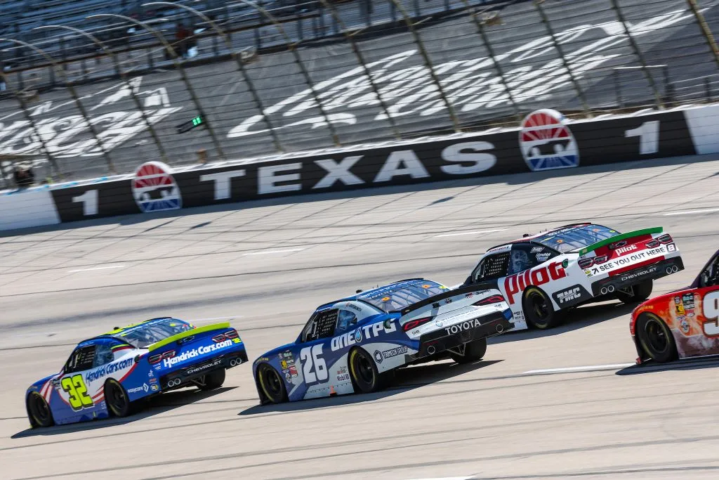
In addition, he noticed that some of the other racers had modified the bodies of their cars for different aerodynamics. Some, like the one shown on this image, have extended flat sections and wings on the rear while others have added canards and splitters to the bodies.

Normally, changes like these that affect how air flows around an object are verified for performance at a wind tunnel. Automotive performance wind tunnels, in particular, are specialty locations designed to imitate the conditions of road driving at different speeds. Special instrumentation and expensive data acquisition systems are usually required in order to get usable results from these types of tests.

Wind tunnels are used to evaluate how air flows around an object
Ryan decided to avoid the high costs and lost time of going to a wind tunnel by doing a study of the car in SOLIDWORKS Flow Simulation.
Testing the Airflow with SOLIDWORKS Simulation
SOLIDWORKS Flow Simulation gave us access to powerful computational fluid dynamics (CFD) analysis capabilities that helped us understand how the air flows across the hood of the car and does indeed reach the intake plane on the hood. The easy-to-use and familiar interface allowed Ryan to set up the conditions that would replicate racing at various speeds.
As our main concern was the airflow reaching the engine hood scoop, Ryan decided to only conduct the study across the front section of the roadster. This will minimize the time and resources for the analysis, yet still, provide the same results as if the whole car had been analyzed.

Simulated Wind Tunnel Test of the Hood in SOLIDWORKS

Flow Study Results showing flow across the hood of the car and into the hood scoop
Step 3: Design
Now that the flow across the hood has been verified, the next steps are to design some guide inlets to make sure that the air entering the hood scoop is making its way to the engine’s intake manifold. We will use SOLIDWORKS for the design and explore a few different manufacturing methods to make sure our design can withstand the grueling demands of the racing world.
Designing the Inlets
Before this project, Ryan has been racing the car in an open-air configuration. Turbulent flow and higher temperatures in the engine bay can affect the air that reaches the intake manifold and take a toll on performance. One approach to solve this is to design a way to increase the flow of air going into the hood scoop rather than directly into the engine.
Having the right geometry is important to ensure that a retrofit design will work. To design the inlets for the engine we could use 3D scanning, but the process would yield a lot more data and information than what is needed for the few angles the modification requires.
After some brainstorming, Ryan decided to use different basic modeling tricks such as Insert Sketch Picture in SOLIDWORKS to make sure that the inlets would fit the engine.

Insert Sketch Picture allowed Ryan to use a scaled picture of the actual manifold during design to ensure precise fitment.
The rest of the inlet design was completed using simple modeling strategies. A mockup of the intake manifold in SOLIDWORKS allowed for the dimensions of the inlets to match exactly the engine configuration. In addition, Ryan decided to design a clamping style collar to allow for easy removal of the parts, if needed.

SOLIDWORKS Assembly showing inlets and collars
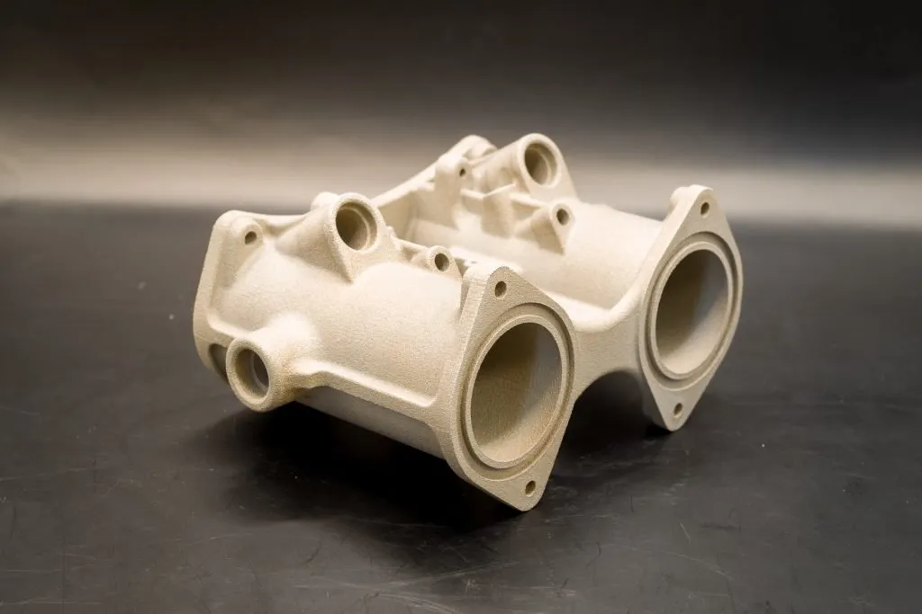
Step 4: Manufacturing
After the design was complete, the next step was to manufacture the inlets. Computer Numerical Control (CNC) machining the inlets from billet aluminum or a similar material would be expensive and time-consuming. A multi-axis machine would increase the production cost tremendously as well as use too much material. Ryan decided to look at TriMech’s line of Stratasys FDM 3D printers to manufacture the inlets. The printer produced a sturdy piece that won’t melt and will direct airflow.
FDM printers have more material options for parts needing greater durability. In this case, we were more concerned with functionality over aesthetics due to the environment in which the inlets will be used. Therefore we decided to make the parts, and a prototype test jig, using one of our FDM printers.

One of the inlets made in a Stratasys FDM Printer, showing model material (blue) and removable support material (black)
Installing and Testing
Before printing out the entire inlet, Ryan wanted to make sure his design was accurate to clamp the pieces to the inlet. He decided to print out an oval that would go into the inlet instead of printing out the entire piece. This helped in avoiding the use of too much support material. This prototyping step helped him confirm the piece was the right size and would fit into the car. Taking this step helped Ryan save time and figure out how to attach the inlet to the car.

Inlets installed on the Hayabusa Engine, with piping to help direct the air from the hood scoop

Ryan installing an inlet on the Thunder Roadster
Related TriMech Solution
Learn more about the solutions featured in this Case Study:
More Case Studies and News Stories
Accelerating Race Ready Engineering Through Digital Twins and Advanced Manufacturing
How Capone Motorsports cut design cycles in half and unlocked new performance potential.
How Sam Hunt Racing Gained Time, Control, and Performance Through In‑House Metrology
A young and punchy NASCAR team builds engineering independence and protects on‑track performance with TriMech and ZEISS.
Get Affordable, High-Performance Metal Parts Quickly Using TriMech’s Cold Metal Fusion Service
TriMech now offers Cold Metal Fusion, a faster and more affordable 3D printing service for creating high-performance metal parts that outperform traditional machining and casting.